My SawStop table saw has developed some small rust spots on the rear of the table. This came from rain blowing through the turbine vent in the garage roof. When I discovered it, I cut a sheet of 1/4" plywood to cover the top when I am not using it. From Stumpy Nubs Woodworking Journal, I found this video:
The difference between amateurs and professionals is that professionals do not point out their mistakes.
Every time I see some making self-deprecating comments at the beginning of a post, I cringe. When someone makes such comments, it immediately tags them as an amateur.
Be a professional. Show your work. Don't criticize it or your skills. There are plenty of naysayers around to do that for you.
My SawStop was purchased mid-2022 and it has never had a tuneup in the true sense of the word. So, this post and others that will be posted subsequently will document that effort
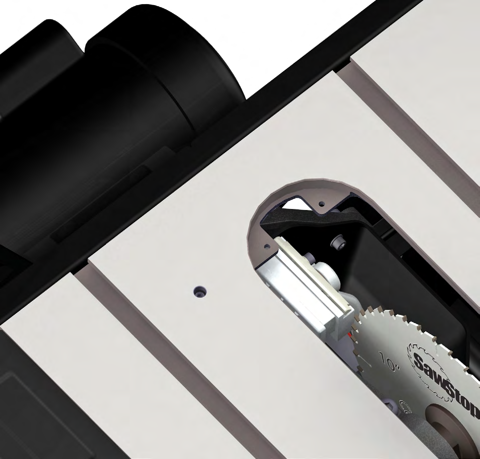
BLADE TO MITER SLOT ALIGNMENT
Using a combination square and feeler gauges, my saw's blade is within 0.006" of being parallel to the miter slot. Tolerance is +/- 0.010 inches. No adjustment is necessary at this time. However, I was unable to find instructions for my CNS saw.
There is an interesting video showing how to fabricate a sled for holding a dial indicator. This is more work than the feeler gauge method. I built this tonight and it works. However, I made a few mistakes that I will correct tomorrow. Lesson: proceed slowly and think through each step. I find that I do much better if I draw up the design in CAD. Then, I can see my mistakes in design beforehand.
UPPER ELEVATION STOP
The upper elevation limit stop is fixed by the set screw in the cast iron table top located to the left of the rear of the table opening (see Fig. 83). The upper elevation limit bolt can be adjusted with the included 3 mm hex key. To lower the maximum blade elevation, adjust the elevation handwheel until the blade elevation is set to the correct maximum height. Thread the set screw in clockwise until it is tight. To raise the maximum blade elevation, begin by turning the set screw counter-clockwise about one complete revolution. Then, adjust the elevation handwheel until the blade elevation is set to the correct maximum height. If the upper elevation limit stop prevents you from raising the blade to the desired maximum elevation, continue to turn the set screw counter-clockwise until the blade can be raised
to the correct elevation. Once the blade is set to the correct maximum elevation, turn the set screw clockwise until it is tight. The upper elevation limit has now been set.
LOWER ELEVATION STOP
To check the position of the lower elevation limit stop, turn the elevation handwheel counter-
clockwise until the blade is lowered all the way. The top of the blade should be approximately
1⁄8 inch below the table top surface. If the distance is approximately 1⁄8 inch, no further
adjustment is necessary. If adjustment is necessary, the lower elevation limit stop is fixed by the M6 socket head screw on the bottom of the rear trunnion (see Fig. 84). The head of the lower elevation limit
screw is painted yellow to make it easier to locate. Loosen the M6 hex nut that locks
the position of the limit screw by rotating it counter-clockwise with a 10 mm wrench. Next, thread the lower elevation screw out counter-clockwise with the included 5 mm hex key at least two complete revolutions. Then turn the elevation handwheel counter-clockwise until the arbor slightly compresses the rubber bumper (see Fig. 85).
ADJUSTING TILT LIMITS
45° Tilt Limit Stop
The tilt limit stops allow you to easily and quickly set the bevel angle to 0° and 45°. However, when making precision cuts, it is always best to check the angle of the blade with a combination square or similar tool. To check the position of the 45° limit stop, install a 10 inch saw blade on the arbor (see page 29). Raise the blade to its full elevation, and turn the tilt hand wheel clockwise until the limit stop is reached. Using a combination square, check to see that the blade is at a 45° angle to the table (see Fig. 88). If you need to adjust the position of the 45° limit stop follow the instructions below.
The 45° tilt limit stop is determined by the set screw in the cast iron table top located to the right of the front of the table opening (see Fig. 87). Use the included 3 mm hex key to turn the screw counter-clockwise several turns.
0° Tilt Limit Stop
To check the position of the 0° limit stop, install a 10 inch saw blade on the arbor (see page 29). Raise the blade to its full elevation, and turn the tilt handwheel counter-clockwise until the limit stop is
reached. Using a square, check to see that the blade is at a 90° angle to the table (see Fig. 86). If you need to adjust the position of the 0° limit stop follow the instructions below. Next, adjust the tilt hand wheel until the blade is at 45° to the table. Turn the 45° limit set screw clockwise until it is tight. The 45° limit stop has now been set.


